
Call Us

(905) 670-0113

Why Choose an Oil Immersed Transformer?

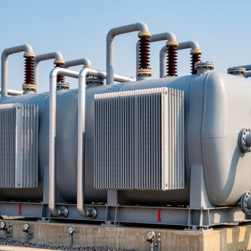
Choosing an Electric Transformer Oil-Immersed Transformer can make sense when dependable cooling and insulation matter in demanding service. Inside the sealed tank, insulating oil surrounds the windings and core. It helps limit electrical discharge and carries heat toward the tank walls or radiators. On a hot afternoon, those radiators can be doing quiet, essential work. The design is common in utility substations, industrial facilities, and other applications that need substantial capacity.

Transformer engineer Martin J. Heathcote, author of The J&P Transformer Book, describes transformer design in detail. A concise paraphrase of the engineering principle reflected in his work is: “Transformer oil provides both electrical insulation and a path for heat to escape.” This is a paraphrase, not a verified verbatim quotation. That distinction matters when technical claims need to be checked.

Oil immersion is not automatically the best choice. Installation space, fire-safety planning, environmental conditions, and maintenance resources all affect the decision. Oil condition needs monitoring, and leaks must be addressed promptly. Still, oil is not magic. A neglected unit can lose reliability, even when its basic design is sound. Buyers should compare the transformer’s rated load, cooling arrangement, protection features, and maintenance requirements with the actual operating site. A qualified engineer can assess those details against the project’s conditions. That careful comparison—not the technology’s name alone—shows whether an oil-immersed unit is a practical fit.
Why Choose an Oil Immersed Transformer?

What an Oil-Immersed Transformer Is and How It Works

Why Choose an Oil Immersed Transformer?

What an Oil-Immersed Transformer Is and How It Works

An oil-immersed transformer places its magnetic core and copper windings inside a sealed tank filled with insulating liquid. The liquid separates energized components and carries heat away from the windings. As it warms, it rises through the tank and radiators; cooler liquid sinks back down. This natural circulation helps control temperature without pumps in many designs. Simple, but not maintenance-free.

IEC 60076-2 sets temperature-rise limits for liquid-immersed transformers, including 60 K for top liquid and 65 K for average winding under specified test conditions. These figures are design limits, not a promise that every unit will run at those temperatures. The U.S. Department of Energy’s 2024 distribution-transformer standards analysis projects about 10.4 quadrillion Btu in cumulative energy savings over 30 years. That figure covers regulated distribution transformers broadly, not oil-filled models alone. Still, it highlights why efficiency deserves attention alongside cooling and insulation.

Tips: Check oil level, leaks, and temperature indicators during inspections. Keep radiator surfaces clear; dust and leaves can impede heat transfer. One detail is easy to underestimate: operating conditions change, so use the transformer’s own nameplate and service records when assessing performance.

Key Components and the Role of Insulating Oil

An oil-immersed transformer uses several parts that work together. The laminated steel core guides magnetic flux, while copper or aluminum windings carry electrical current. Insulating oil surrounds these active parts inside the tank. Radiators or cooling fins help release heat, and bushings provide insulated paths for external connections. Some designs also include a conservator and breather to manage oil expansion and limit moisture entry.

The oil has two essential jobs: electrical insulation and heat transfer. It fills gaps around the windings, helping prevent unwanted electrical discharge. As the transformer operates, the oil absorbs heat and carries it toward the tank walls or radiators. Small details matter. Moisture, oxidation, or contamination can reduce insulating performance over time. One limitation is easy to miss: oil quality may change before any visible problem appears. Testing and maintenance records provide useful evidence of its condition.

Tips: Check the oil level, temperature indicators, and visible joints during routine inspections. Look for leaks near gaskets and valves. Follow the equipment maker’s maintenance guidance, and arrange oil testing when operating conditions or inspection results call for it. A clean-looking tank is not a complete condition check.

Cooling Methods and Operational Performance

Why Choose an Oil Immersed Transformer?

Cooling Methods and Operational Performance

Oil-immersed transformers move heat from windings into insulating liquid, then release it through the tank and radiators. In ONAN designs, oil and surrounding air circulate naturally. ONAF adds fans to increase airflow across the radiators; larger units may use pumps for forced oil circulation. During a hot afternoon peak, that extra airflow can help control temperature without changing the electrical load. The trade-off is real: fans and pumps need inspection, and natural cooling alone may not keep pace with every overload.

Temperature is a useful operating signal. IEC 60076-2:2011 specifies a 60 K limit for top-liquid temperature rise under its stated test conditions. IEEE C57.91-2011 models insulation aging against winding hot-spot temperature, using 110°C as a reference for normal insulation life in its standard thermal-aging model. These are benchmarks, not guarantees; ambient heat, loading, oil condition, and cooling equipment all affect actual performance. Check radiator surfaces, fan operation, oil leaks, and temperature readings during routine rounds. Small details matter. A blocked radiator can quietly reduce heat transfer, while a failed fan may go unnoticed until demand rises. Oil cooling is effective, but it is not maintenance-free.

Why Choose an Oil Immersed Transformer? - Cooling Methods and Operational Performance
Cooling Method Oil and Air Circulation How Heat Is Removed Operational Performance Considerations
ONAN Oil circulates naturally inside the tank; air circulates naturally around the radiators. Transformer losses heat the insulating liquid, which rises and transfers heat to the tank or radiators. Cooler liquid returns by natural convection. Provides cooling without powered fans or oil pumps. It is commonly used where a simple, low-auxiliary-power arrangement is suitable. Cooling capacity depends on natural circulation and the available radiator surface. The permissible rating is set by the transformer’s design and temperature limits.
ONAF Oil circulates naturally; fans force air across the radiators. Forced airflow increases heat transfer from the radiator surfaces to the surrounding air. Fan operation can provide an additional cooling stage and support a higher rating than the same design’s natural-air stage, when specified by the manufacturer. Requires fan power and routine checks of fans, controls, and alarms. Fan failure may reduce the available rating to the applicable natural-cooling stage.
OFAF Oil is circulated by pumps; air is forced across the radiators by fans. Pumped oil moves heat to the radiators, while fan-driven airflow removes heat from the radiator surfaces. Provides active oil and air circulation, which can enable higher cooling capacity in a design intended for forced cooling. Depends on both pumps and fans, so auxiliary power, control equipment, and maintenance requirements are greater than for natural-circulation methods.
ODAF Oil is pumped through defined paths directed toward the windings; fans force air across the radiators. Directed oil flow carries heat away from winding regions, and forced air removes heat at the radiators. Designed to improve oil flow through targeted winding cooling paths. Its performance depends on the winding and oil-duct design as well as the cooling equipment. Requires pumps, fans, controls, and monitoring. The directed-flow arrangement must be designed for the specific transformer; it is not a universal retrofit feature.
Cooling-code descriptions are general. Actual loading capability, temperature rise, auxiliary equipment, and operating limits depend on the transformer’s design, nameplate ratings, ambient conditions, and applicable standards.

Benefits and Limitations Compared with Dry-Type Transformers

Why Choose an Oil Immersed Transformer? Benefits and Limitations Compared with Dry-Type Transformers

Oil-immersed transformers use insulating liquid to carry heat away from the windings. That cooling can support compact designs and substantial loads, especially outdoors or in utility yards. Dry-type units avoid liquid handling, which can simplify indoor installation where spill containment is difficult. They still need clear airflow and suitable fire protection. No transformer is maintenance-free.

Loss figures complicate the comparison. EU Ecodesign Regulation 548/2014 sets different maximum-loss values for 1,000 kVA units: its listed Tier 1 limits are 810 W no-load and 7,600 W load loss for liquid-immersed models, versus 1,550 W and 9,000 W for dry-type models. These are regulatory limits, not a guarantee of a specific unit’s performance; check the nameplate and test data. Oil also means inspections for leaks, liquid condition, and containment. Dry units avoid those tasks, but may need more ventilation and can be louder in enclosed rooms. The right choice depends on site conditions, duty cycle, and service access. I would not decide from purchase price alone.

Why Choose an Oil-Immersed Transformer?

How to read this chart: Ratings are qualitative (1 = less favorable, 5 = more favorable) and summarize common design trade-offs—not measured performance or a guarantee for a specific transformer. Actual results depend on the design, rating, installation, and operating conditions.

Common Applications and Selection Considerations

Oil-immersed transformers are commonly used in utility substations, industrial plants, and renewable-energy sites. Their insulating oil helps transfer heat from energized components to the tank and radiators. On a hot summer afternoon, radiator clearance and airflow can affect operating temperature.
That detail matters.

Start selection with the actual load profile, not just the nameplate rating. Compare peak demand, daily load changes, future expansion, and motor-starting requirements. Check primary and secondary voltages, frequency, impedance, tap range, and connection arrangement. A factory with large motors may need different impedance and capacity choices than a small distribution site.
Not always.

Cooling method, ambient temperature, altitude, installation space, and noise limits also deserve attention. Confirm access for oil sampling, leak inspection, and radiator cleaning before choosing a location. Consider suitable containment and fire-safety measures under applicable site requirements. A tidy spreadsheet can still miss a crowded service aisle or a load that grows faster than forecast. Recheck assumptions with operating staff, especially when seasonal demand or harmonics are involved.